Internal crystallization method
1.
Introduction
Single-crystalline
eutectic oxide fibres are needed to reinforce metal,
intermetallic and ceramic matrices to obtain high temperature composites.
2.
The fundamentals of the internal
crystallization method
The method of internal
crystallization was developed in Laboratory of Reinforced Systems of Solid
State Physics Institute initially to produce oxide-matrix/molybdenum-matrix
composites, which were considered mainly as model ones. The concept of the
method is illustrated in Figure 1.
Figure 1. Schematic of the
internal crystallization method (ICM).
First of all a molybdenum
carcass with continuous cylindrical channels is obtained by diffusion bonding
of an assemblage of molybdenum wires and foils. The carcass is then put into
contact with an oxide melt; capillary forces yield the infiltration of the
channels with a melted fibre material. The oxide/molybdenum block is then
moved to a cold zone of the furnace to crystallize the fibres. This is the
basic scheme of the ICM [5 ,6], a variation of the basic scheme with single
crystalline seeds at the top of the carcass (Figure
2) allows obtaining a fibre set of a homogeneous crystallographic
orientation [8]. The final step in the obtaining fibres process is dissolution
of molybdenum in an HCl/HNO3/H2O mixture.
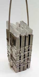
Figure 2.
A set of the molybdenum
carcasses with seeds at the top.
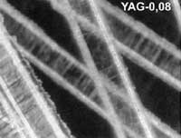
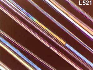
A variety of the oxide fibres,
such as sapphire [8 ] and YAG [9 ] of a homogeneous crystallographic
orientation alumina-YAG eutectic [7 ], and single crystalline mullite [10 ]
have been obtained by using the method.
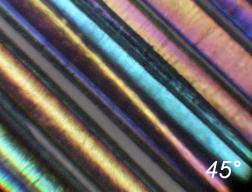
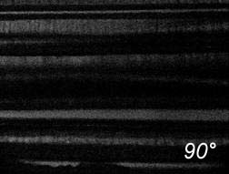
Some illustrations of the fibres obtained are presented in
Figure 3
.
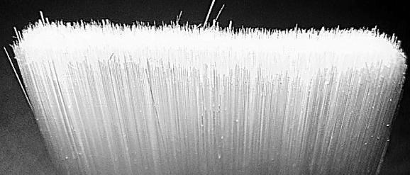
A bounded
bundle of sapphire fibres.
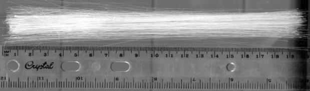
A bounded
bundle of sapphire fibres.