|
© Song Ltd
Moscow and Chernogolovka
1990-2003
|
|
Generator
components
Technical potentialities
Technical specifications (in detail)
Major
technical specifications
| Power |
100
kW |
| Frequency |
20-40
Hz |
| Output
voltage |
to
500 V |
| Voltage
control of power |
| Galvanic
isolation of the output |
| Air
cooling |
| Overall
dimensions |
800x800x1050
mm |
| Weight |
160kg |
(The
characteristics of the generator are detailed below)

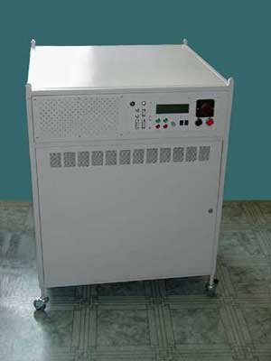
Transistor power
generator of alternating voltage
Until
recently, two types of generators have been widely used for induction
heating. These are thyristor inventers and high-frequency lamp generators
or motor-generators.
Long times of
thyristor commutation limit their use at frequencies higher than 10 kHz.
Lower frequencies allow the use of thyristor inverters with a fairly high
efficiency coefficient. High frequency lamp generators, on the contrary,
are not frequency-limited, but the life-time of powerful lamp operation is
only 5000 to 7000 hrs and their efficiency coefficient is rather low (hot
higher than 65%). Their weight, power, and overall dimensions may also
limit their application.
|
|
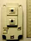
Lately,
a new class of power devices have appeared, whose characteristics
meet the requirements of designers of power setups. These are power
transistors produced by MOS technology (MOSFET and IGBT) and working
at frequencies up to 150 kHz. They made the basis for developing
highly efficient powerful generators and secondary power supply
sources that are superior to devices based on vacuum lamps and
thyristors.
As compared to lamp generators, transistors ones have a higher
efficiency coefficient, longer service life, smaller overall
dimensions and weight. As compared to thyristor generators, they
work at much higher frequencies, which facilitates the solution of
galvanic isolation of the power unit in crystal growth setups. |
|

|
The Firm
has designed and tested on IGBT-transistors power generator
operating at middle-band frequencies for an automatized setup for
single crystal growth in order to improve the technical and economic
parameters and expand functional potentialities of the generator and
setup.
Various circuit design of the generator power unit and control
algorithms were tested and methods of calculation and elaboration of
generators with 100 kW (and higher) power output were developed.
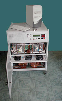
Latest IGBT transistors and specialized riskprocessors made
the elemental basis of the power unit, and a commercial PC placed
inside the generator was used in the system of operation, control,
and testing. |
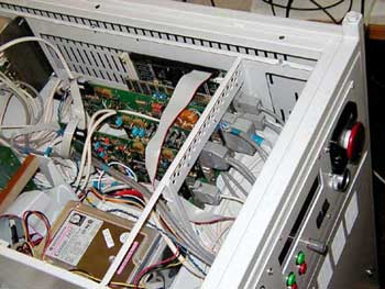
Component
Units of the Generator
|
|
|
|
|
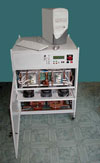
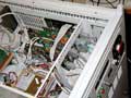
| The
generator consists of a case, which houses the power and operation
units of the generator as well as control, indication, and measuring
devices. Some of power capacitors, which are constituents of both
the generator and the power circuit, are placed next to the inductor
of the setup for single crystal growth |
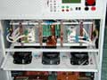
1.1
The power circuit includes
- A power automatic switch and a contactor
- A semiconductor rectifier unit
- Power elements of the current supply circuit
- A transistor inverting amplifier unit
- A power smoothing choke
- A separation power transformer
- Power capacitors |
1.2
The control system includes
- Electron supply plates
- Electron plates to control the power rectifier and the inverting
amplifier
- Electron plates to match input and output signals
- Current, voltage, frequency, etc. sensors
- A commercial PC-based system to process information and control
the generator |
1.3
Information imaging system consists of
- A graphic display on the generator panel
- A monitor screen, when an auxiliary computer is used |
Technical
potentialities:
1.1 Major
features
- Galvanic isolation from the supply line
- Computer self-testing and heat control
- Computer analysis of the external circuits (determination of the
resonance frequency and high quality of the power circuit
- Automatic resonance tuning and automatic frequency matching in the
process of operation
- Pre-start control programme: step by step diagnostics of all units and
imaging of malfunctions on the graphic display
- Programme for external circuit analysis
- Keeping a log of processes
- Information exchange with an external PC through a standard RS-232
channel
- Programming of output parameters, which allows the generator to be used
in other setups and devices without changing its apparatus part
1.2 Loops of
reverse connection (regulation)
- DC power
- Power circuit current (output power)
- Automatic resonance frequency matching
1.3 Controlled
and Controlling signals and ways of galvanic isolation
- A contractor, a controlled rectifier, phase control, DC parameter
measurements
- An inverting amplifier (current signal from the keys: overload, through
current), and a frequency meter
- Working load voltage and current (resonance phase detector)
- External signals: power circuit inductor current, external sensor
signal, external blocking
- Thermo-sensors, internal blocking
2.Technical
Characteristics:
2.1
Electricity supply for the generator - 3-phase 380V line , 50 -60 Hz
frequency.
2.2 Data-sheet output power of the generator - not less than 80kW.
2.3 Output power regulation range - 5 to 100%.
2.4 Limiting departure of the data-sheet output power from the pre-set one
- not more than 0.01%. The accuracy of power maintenance (current in the
power circuit) -30W at 60kW output power.
2.5 Output voltage frequency - 8 to 50kHz with automatic adjusting,
data-sheet output voltage - 300V (up to 500V).
2.6 Generator efficiency coefficient at the data-sheet power - not less
than 94% (Transformer not taken into account).
2.7 Generator output circuit is isolated from the supply line and the
grounding circuit.
2.8 Grounding conductor resistance must be less than 0.1Ohm and have an
insulating coating.
2.9 The generator has two modes of setting the output power:
"Local" and "Remote".
The "Local" mode is initiated by the potentiometer on the
generator panel. In the "Remote" mode, the signal comes through
an analog 0-10V input from the indication device or from an auxiliary PC.
In the "Remote" mode, the generator starts operating after the
signal "Ready" by locking the contact usually in the unlocked
state, and stops operating by unlocking the contact "Ready".
2.10 Generator has an analog 0-10V output signal proportional to the
output power.
2.11 Generator has relay output signals
- signal "Blocking" for opening any of the generator gates
- signal "Protection", an alarm signal for change of state in
any of generator protection systems
- signal "Cooling", an alarm signal for the cooling system
2.12 Generator has a conventional RS-232 interface connecting it to the
controlling PC.
2.13 Generator has forced air cooling.
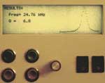
2.14 Measuring devices on the generator front panel and indication devices
on the graphic display provide information about
- voltage on the power rectifier output
- current on the power rectifier output
- transformer output power
- transformer output frequency
- graphic presentation of the inductor resonance curve and basic resonance
parameters.
2.15 Generator has integral protection systems against
- phase breakage of power supply voltage
- excess of current, voltage, and temperature of power elements
- lowering of water pressure below the fixed level
- excess of water pressure above the fixed level
- blocking of the opening state of the generator case doors.
2.16 Barrage voltage on the generator input does not exceed values stated
in GOST 23450-79 "Noise Backgrounds Permissible for Industrial,
Scientific and Medical Installation". The noise level is not higher
than 60dB.
2.17 Generator is housed in a double-acting 800*800*1000mm .
2.18 Total length of current-carrying cables does not exceed 10m.
2.19 Generator id to be operated indoors under conditions corresponding to
M6 GOST 175116-72 (under temperate climate conditions).
2.20 Weight - 160kg. |